
Electronic Calling Bell Circuit Diagram Circuit Diagram
Using nRF24L01 2.4 GHz module. We will be constructing a simple wireless calling bell using Arduino and nRF24L01 2.4 GHz module, which can work around your home or your office without any hiccups or coverage issue. The proposed circuit can be powered from a 5V smartphone adapter or any inexpensive 5V adapter which keeps your circuit alive and.

how to connect calling bell wiring diagram YouTube
The bell can work on 1.5V or 3V, using one or two pencil cells, and can be used in homes and offices. Musical call bell circuit. Two transistors are used for sensing the finger touch and switching on a melody IC. Transistor BC548 is npn type while transistor BC558 is pnp type. Musical call bell circuit

Calling Bell Circuit Diagram
Let's Build our Simple Tone Generator. Here we present a simple and low-cost tone generator circuit, a ding dong bell suitable for calling bell purposes. It is made around IC 8021. It is an 8 pin IC but only four pins are shown here. 8021 has an in-built circuitry to produce ding dong sound each time its pin 3 is pulled low.

Electric Bell Circuit Diagram
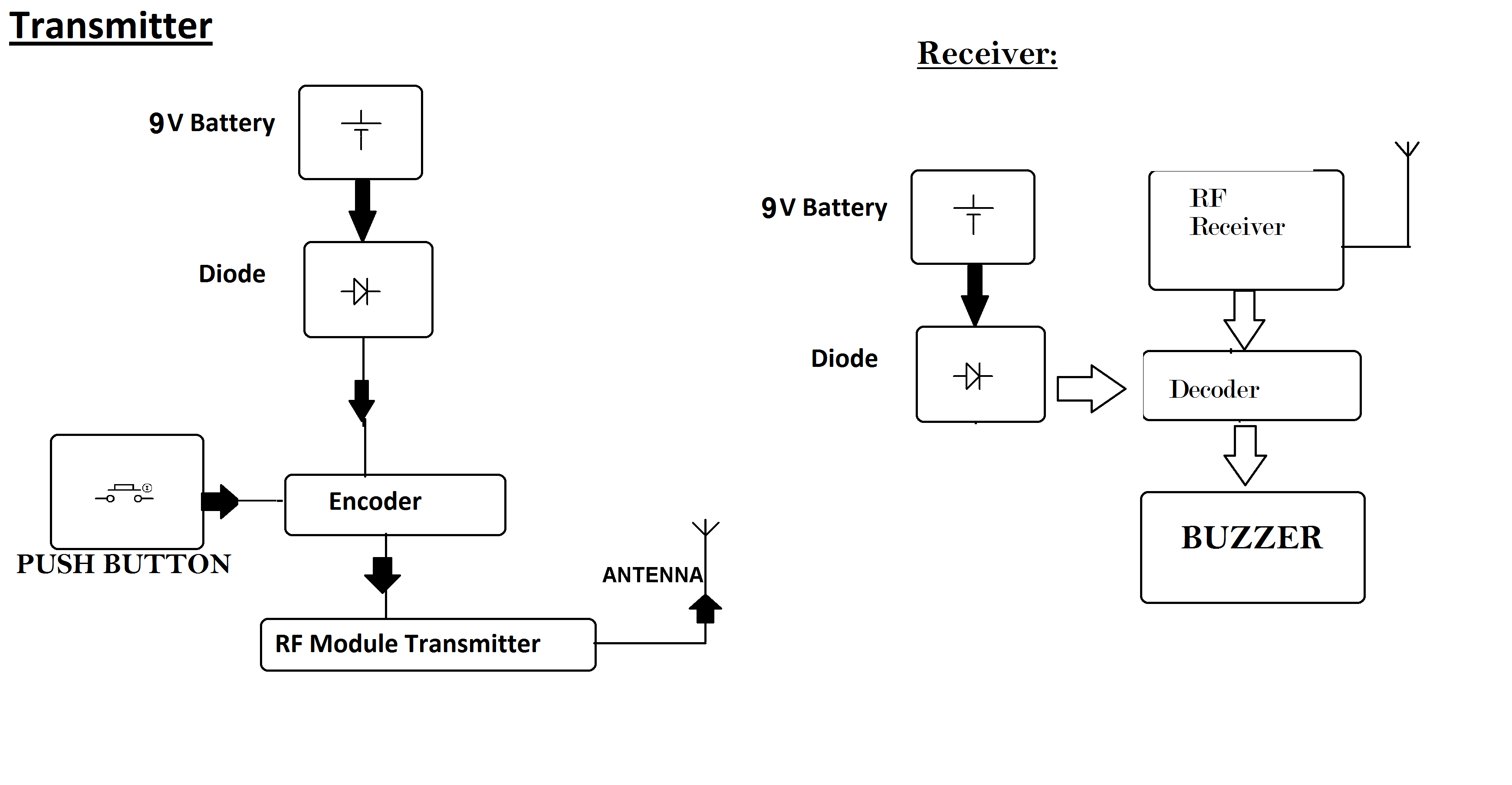
Wireless Call Bell - Circuit Diagram. Transmitter; Receiver; Working and Functioning; PCB Circuit Design; Step-by-step Instructions to make this Wireless Call bell; Other DIY Doorbell Projects; The prototypes for the author's transmitter and receiver are depicted in Fig. 1 and 2 respectively.

Detailed Diagram of Calling Bell, and Buzzers etc. YouTube
Step 4: Uploading the Code. Download the arduino software. Download the Digispark attiny driver file above if you are going to use the digispark usb attiny microcontroller or you can just skip the installation process (steps 2, step 3 and step 4) of the drivers if you are going to use a nano. Now click Files>Preferences and then in the text.
circuit diagram of doorbell
A call bell sometimes called a counter bell service bell or concierge bell is a bell that alerts and causes attention to the attendant who hears it.how call.
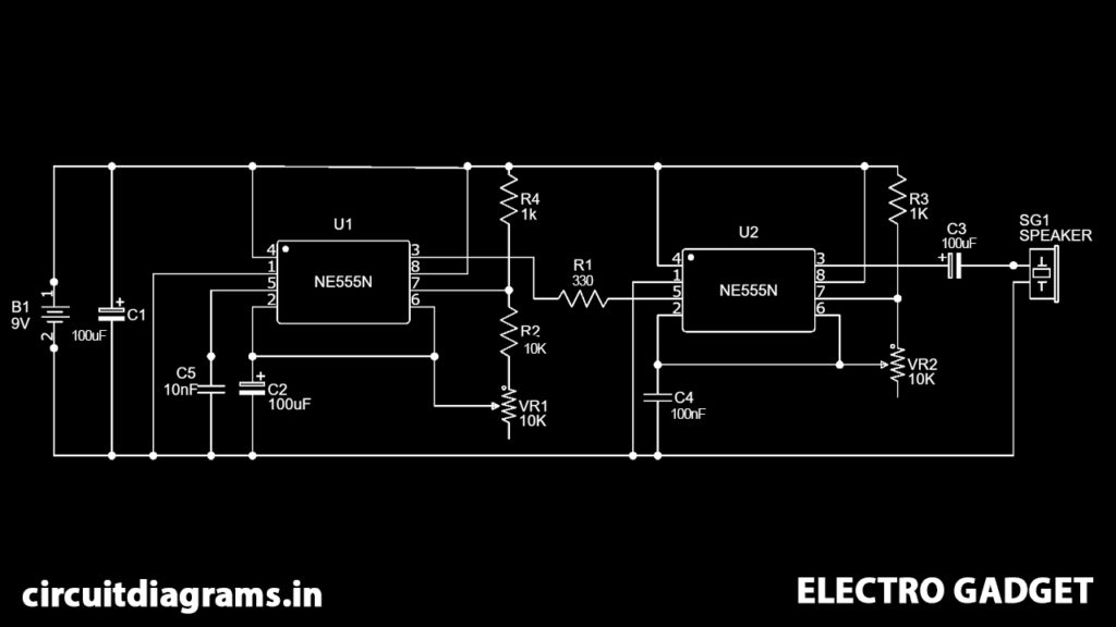
Ding Dong Calling Bell Circuit Using 555 Timer Electro Gadget
The electric bell is a simple circuit that triggers a sound on the completion of the circuit by pressing the button. It is this simplicity that makes the doorbell such a marvel. The simple devices in the doorbell but the scientific principle of electromagnetism into action in a useful way. Q2.
Call Bell Circuit Diagram
Principle Behind This Calling Bell Circuit. This circuit chiefly comprises two 555 timer clock ICs. First IC is worked in astable mode and the frequency of the second IC is tweaked by the first IC. For that, the output pin of the first IC is associated with the fifth pin of the second IC. The first IC is worked at a frequency of 1Hz.
15 Calling Bell Circuit Diagram Robhosking Diagram
As businesses become increasingly reliant on technology, remote calling bell circuits are becoming more and more popular. With these advanced systems, you get the convenience of a traditional doorbell with the added benefit of being able to be notified from anywhere in the world.The concept of a remote calling bell circuit is fairly simple. A transmitter is placed… Read More »
)/help file/BellwCustomWiring.gif)
Bell Scheduling and Setup for the Reader
#btmtech#diyprojects#electronics #btmtech #btmtech #btmtechvideos https://www.youtube.com/channel/UCz-mIyWq9pl4Xm4u0iS4p_A?sub_confirmation=1This video expla.

Calling bell wiring connection at home YouTube
Calling Bell: This is a very simple circuit consisting of only two components, a three pin ic UM66 or BT66 and a transistor BC548. this is a very easy method to make a calling bell. the circuit can be made without soldering also. i used a cassette…

Home Calling Bell Wiring Diagram Caret X Digital
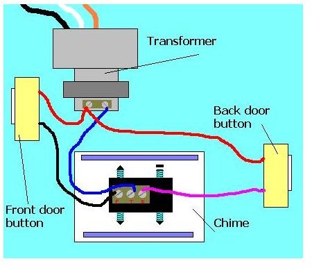
A home calling bell wiring diagram is your guide to understanding the components of a calling bell system and how they fit together. The diagram outlines the individual components used to create the system and the path that electricity takes to power it. You can also see which wires connect to each component, allowing you to troubleshoot any.
.jpg)
15 Calling Bell Circuit Diagram Robhosking Diagram
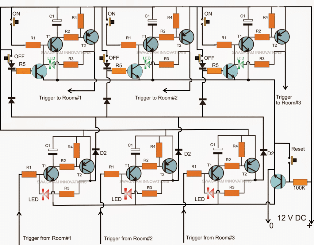
The circuit implementation of the proposed office call bell monitor network can be done by using a group of set/reset flipflops as may be witnessed in the following diagram: Circuit Diagram. The circuit above illustrates an example wiring for three office rooms which may be extended to any desired numbers simply replicating the stages. How it Works
Electrical and Electronics How Does A Calling Bell Work?
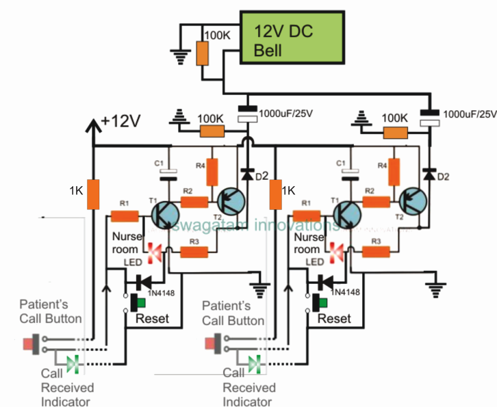
Circuit Diagram. All R1 = 100 k All R2, R3, R4 = 10 K All diodes = 1N4148 All C1 = 100uF/25V All NPN = BC547 All PNP = BC557. Working Explanation. This Office Call Bell Network Circuit with LED Monitor is a system designed for offices to communicate with each other easily. It consists of three identical modules containing two NPN transistors.

Calling Bell Circuit Diagram Pdf
The transistor 9013 is used to amplify the output of IC to drive an 8 ohms speaker. You can also use substitute transistor in the place of 9013. The circuit will produce ding dong bell sound by pressing the switch near the 1N41418 diodes. The operating voltage of the circuit is 4.5 volt DC.

Home Calling Bell Wiring Diagram
Fig. 3: Circuit diagram for Multi-User Call Bell. Working of the circuit is simple. When, say, room number 1's switch S1 is turned on, its LED1 glows and DIS1 displays 1 besides sounding an alarm through piezo buzzer PZ1. The caller should switch off S1 after the call has been attended so that the system is ready to receive the next call. Fig.